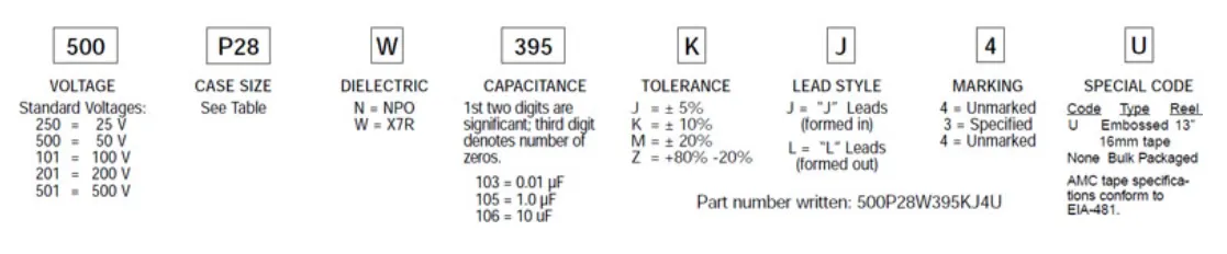
Mini-Switchmode® Capacitors
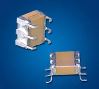
JDI's Mini-Switch Mode® ceramic capacitors combine the advantages of high capacitance found in tantalum capacitors with very low ESR performance of ceramic capacitors. The "J" and "L" lead configurations replace 1825 and 2225 SMT chips to provide stress relief and prevent cracking due to thermal cycling or mechanical board flexing. Another plus of the J-lead style is that this configuration allows use of the same solder lands as the SMT chips. See the Switch-Mode section for larger values. See also the Technical Notes on soldering and handling and suggested solder lands.
Capacitance Values
| Size Code | EIA Chip Size | NP0 Max Capacitance (μF) | X7R Max Capacitance (μF) | ||||||||
|---|---|---|---|---|---|---|---|---|---|---|---|
| 25V | 50V | 100V | 200V | 500V | 25V | 50V | 100V | 200V | 500V | ||
| P09 | 1825 | 0.056 | 0.047 | 0.039 | 0.027 | 0.018 | 1.5 | 1.2 | 0.75 | 0.56 | 0.27 |
| P29 | 1825 | 0.11 | 0.094 | 0.078 | 0.054 | 0.036 | 3.0 | 2.4 | 1.5 | 1.1 | 0.54 |
| P39 | 1825 | 0.16 | 0.14 | 0.11 | 0.081 | 0.054 | 4.5 | 3.6 | 2.2 | 1.6 | 0.81 |
| P49 | 1825 | 0.22 | 0.18 | 0.15 | 0.10 | 0.007 | 6.0 | 4.8 | 3.0 | 2.2 | 1.0 |
| P08 | 2225 | 0.068 | 0.056 | 0.047 | 0.033 | 0.027 | 2.7 | 2.2 | 1.5 | 1.2 | 0.39 |
| P28 | 2225 | 0.13 | 0.11 | 0.094 | 0.066 | 0.054 | 5.4 | 4.4 | 3.0 | 2.4 | 0.78 |
| P38 | 2225 | 0.20 | 0.16 | 0.14 | 0.010 | 0.081 | 8.1 | 6.6 | 4.5 | 3.6 | 1.1 |
| P48 | 2225 | 0.27 | 0.22 | 0.18 | 0.13 | 0.10 | 10 | 8.8 | 6.0 | 4.8 | 1.5 |
Mechanical Specifications
| Dimensions Applicable to specific sizes: |  |  |  |  |
||||||||||||||
| in. | mm | |||||||||||||||||
| h ± .010 | .070 | 1.78 | ||||||||||||||||
| c Typ. | .100 | 2.54 | ||||||||||||||||
| p ± .015 | .065 | 1.65 | ||||||||||||||||
| Dimensions Applicable to specific sizes: | P08 | P09 | P28 | P29 | P38 | P39 | P48 | P49 | ||||||||||
| in. | mm | in. | mm | in. | mm | in. | mm | in. | mm | in. | mm | in. | mm | in. | mm | |||
| L max | .280 | 7.11 | 0.24 | 6.1 | 0.28 | 7.11 | 0.24 | 6.1 | 0.28 | 7.11 | 0.24 | 6.1 | 0.28 | 7.11 | 0.24 | 6.1 | ||
| W max | .270 | 6.86 | 0.27 | 6.86 | 0.27 | 6.86 | 0.27 | 6.86 | 0.27 | 6.86 | 0.27 | 6.86 | 0.27 | 6.86 | 0.27 | 6.86 | ||
| T max | 0.95 | 2.41 | 0.095 | 2.41 | 0.19 | 4.83 | 0.19 | 4.83 | 0.285 | 7.24 | 0.285 | 7.24 | 0.38 | 9.65 | 0.38 | 9.65 | ||
| Note: J-Lead and L-Lead options are available on all sizes above | ||||||||||||||||||
Electrical Specifications
| X7R | NP0 | ||
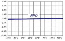
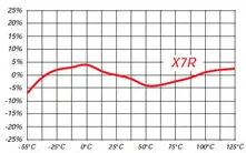
| TEMPERATURE COEFFICIENT: | -55 to 125° | 0 ± 15% | 0 ± 30ppm/°C |
| DISSIPATION FACTOR: | 1kHz, 25°C | 2.5% max | 0.1% max |
| AGING RATE: | % per decade hour | 2.5% | none |
| INSULATION RESISTANCE: | 1000⟨F or 100G⟨, whichever is less at rated WVDC, 25°C | ||
| DIELECTRIC STRENGTH: | For 500V Ratings 750VDC, 25°C, 50mA max For 200V Ratings 2xWVDC, 25°C, 50mA max For 25-100V Ratings 2.5xWVDC, 25°C, 50mA max |
||
| CAP & D.F. MEASUREMENTS: | 1kHz ±50Hz; 1.0±0.2 VRMS, 25°C | ||
Key Features:
- Stress Relief from Cracking due to Thermal Cycling, TCE Mismatches or Board Flexing
- 25 to 500 VDC Ratings
- Custom Sizes, Voltages, and Values Available
- Ideal for DC-DC Power Supply Applications
General Specifications:
- Stress Relief from Cracking due to Thermal Cycling, TCE Mismatches or Board Flexing
- 25 to 500 VDC Ratings
- Custom Sizes, Voltages, and Values Available
- Ideal for DC-DC Power Supply Applications
The legacy info below is for reference only.
Johanson has instituted a new Global Part Numbering (GPN) system.
Only the part number is changing. The parts are produced with the exact same materials, manufacturing processes, manufacturing controls, dimensions, physical attributes and testing as the parts supplied with the legacy part numbers.
The GPNs will be phased in over the next several years and are planned to be completed by January 1, 2026.
We will continue to quote and accept orders with the current (legacy) part numbers throughout this period.
Beginning January 1, 2022, all samples will be provided with the GPN.
Updates associated with this change will occur periodically.
A database for the approximate 2 million crosses can be accessed at: https://www.johansontechnology.com/pn-search